Pages

Monday, October 28, 2013

My new printer (Mendel90)

I eventually got to take an overview picture of my new printer. Up until now, recent posts have only shown various close-ups so I thought a full photo would be nice.

It's a Mendel90, scratch built (not from kit). My other printer, a Prusa Mendel, was used to print all the plastic parts for this one. The sheet material (aluminium composite sheet), and some other parts were sourced locally. Motors and electronics were ordered on-line. I used white sheet material with black plastic parts and motors for a nice contrast in appearance. It currently has a single extruder, a j-head, but its flexible design will allow it to adapt going forward as enhancements evolve.
It prints very well and is faster and more precise than my older printer. My new electronics also allows greater automation than I've previously had. In contrast to my older printer, this one has integrated management of the heated bed, and even have automated cooling of the finished work via a large fan to the rear.

I'm very grateful to Nophead from the RepRap community for sharing his plans and build instructions. I enjoy the challenge of scratch building these devices, but can honestly say that unless you already have some tools and equipment there is little or no saving in comparison to buying a printer kit, but building your own printer, either from kit or otherwise, IS an excellent and rewarding learning experience.  

The Squirrel (Red) courtesy of MBCook on Thingiverse! :-)


Tuesday, October 22, 2013

Insulating the heater block... more data!

I recently posted on the topic of Insulating the Heater Block and a few days later received some great data (graphs) from Alzibiff, a Mendel90 owner and keen RepRaper. Alan (Alzibiff) was in the process of insulating his J-Head heater block with some silicone tape, as per Nopheads design improvements, when he kindly captured some before & after data. This is great data in many ways. I hope I can do its interpretation justice...

{By the way, Alan is the proud owner of that 'pin-up' of 3D printers, the Black Dibond one with the Christmas Tree, which famously featured on the cover of the Mendel90 build manual for some time!)

The target temperature for all graphs was the same, 220 Deg C. The power resistor in the J-Head v5b, running on 12v, had no difficulty bringing the heater block up to temperature in all tests. The significant observable differences between graphs was in the average % power draw, the blue line along the lower (green) graph in each case. Alan has two fans on his x-carriage, one ducted under-carriage PEEK cooling fan (same as this), which I'll call the "Upper Fan". He has a standard M90 work cooling fan, which I'll call the "Work Fan". The latter fan duct was unmodified, no insulation cooling hole (another of Nopheads mods.)

Small Tech Note: I've checked that the power draw of the fans do not impact on the power graph. It only shows % power draw by the heater.

Figure 1. No (heater block) Insulation, Upper Fan ON, Work Fan OFF. 45% power to maintain temp.
Figure 1

Figure 2. No (heater block) Insulation, Upper Fan ON, Work Fan ON. 55% power to maintain temp. This is interesting because it's suggesting there is extra power needed to maintain temperature when the Work Fan is on. There must be air drift from the downward facing cooling fan that is impacting on the heater block, causing it to draw more power to maintain temperature.
Figure 2

Figure 3. Heater block insulation fitted (Silicone Tape), Upper Fan ON, then Work Fan ON at the '31' mark, so both fans on for the latter half of the graph. 38% power (Upper Fan ON), 48% power (both ON), approximately.The power draw to maintain temperature after the insulation is fitted to the heater block is nicely reduced. The insulation is doing it's job. But, once the Work Fan cuts in the power usage increases again slightly. This suggests that cool air drift from the work fan is cooling the heater block somehow. I expect the heater block would benefit from some insulation on it's base also, to further improve the insulation, but the nozzle probably doesn't protrude enough to permit this with the present j-head design.
Figure 3

Figure 4 is probably the most impressive. It shows the insulated heater block in operation with both fans OFF. To me it's the most impressive because the power draw (green graph) is barely above 25%. It shows that the silicone tape is a very good insulator, and really outperforms my skinny Teflon jacket. I must add that this particular test (Fans off) did unease Alan, and he didn't run it very long as he has had his share of extruder jams in the past.
Figure 4

Quick Conclusions:
The silicone tape is an excellent insulator, and an enhancement worth considering.
Indirect cool air (air drift) from fans has a greater impact on the power required to maintain hot-end temperatures than one might think, due to the cooling effect of such air.

Thanks to Alan for the graphs. Hope folks found it of interest. Questions and comments welcome as always.
Regards,
NumberSix


Sunday, October 20, 2013

Print Bed levelling: 3 versus 4 support points...


The importance of a well levelled print bed can not be emphasised enough. The lower the layer height you print with the more critical having a perfectly level print bed becomes for trouble free adhesion of the first layer. The use of a Raft or even altered first layer width or thickness is often a compromise for imperfect bed levels or surface flatness. This is functionality accommodated within slicing packages, e.g. Slic3r. I've never had much success with rafts as they have always proven difficult to detach from the printed object. Rafts are commonly used in commercial printers and also successful on the UP! printer, but the secrets of good raft separation still seems to elude the OpenSource community, it being theorised to be perhaps both material and software related as discussed here by Nophead, although Chris' desire to get to the bottom of this does extend to having good peel-away support, not just raft.

I think, in printers where the print bed is typically un-clipped to remove the finished work, the precise levelling of the print bed can't always be guaranteed so rafting is a good compromise. If you don't want to use rafts or alter the first layer width/thickness then a very level print bed is essential for good contact of the first layer.

I opted to use the Helios Heated Print Bed (HPB) in my scratch-build Mendel90, instead of the more popular Prusa HPB (typically red). I have a Prusa HPB already so its interesting to compare.

My initial expectation was that the Helios would be even more suited to 3 point support and the inherent ease of levelling that brings. The Helios board is twice as thick as the Prusa board. However, I think my expectations have risen over time, and in borrowing a dial gauge to level the new M90 Print Bed I was disappointed by not being able to get it as level as I'd hoped with just three points of support. The problem came down to a slight warp in the HPB, which can't really be described as a fault, as the the deviation is only about .2mm along one edge that was only supported in the middle.

Perhaps if I used thicker glass then the clamps would pull the board straight and leveling would be fine with three point levelling, but I am happy with my light glass (1.3mm thick), as it keeps the overall print bed weight and inertia down.
The Helios comes with long M3 counter sunk screws, some washers, spring washers and nuts. I like the ease of adjustment that spring loading the bed brings, but you have to use strong springs here to avoid wobble.
Photo showing counter sink screw, washers and bolts that come with the Helios board. I use a strong spring (also shown). The Helios fittings are stainless steel which conducts less heat, a good think in this situation.
An essential prerequisite is that the x-axis has been levelled with respect to the printer base. This can be done with a vernier callipers (see photo above), moving the callipers from left to right and turning the Z leadscrews independently of each other, until the x assembly is perfectly parallel to the base.

To hold the dial gauge to the x-carriage I printed off Nopheads dial gauge holder. If your dial gauge has a narrower (8mm shaft) this other clamp may fit better (http://www.thingiverse.com/thing:92852).
You don't have to have a dial gauge to level the bed but it's more time efficient if you have access to one. You can level the bed by using a sheet of paper or feeler-gauge to set the gap under the nozzle at various locations around the bed, and adjusting the bed height until the gap is consistent.

I did some video recording while adjusting the bed level, and generally checking the level after adjustment. I'm sharing an edited down version of my recordings below. It is not intended as an instructional video so don't view it as such. In the first section you will see me adjust the nuts to raise or lower the bed. There is only .1mm between each of the visible numbers on the dial gauge, and the smaller incriments are just .01mm, but what I concluded by the end of the first section was that I was not going to level the bed on the right hand edge. The second section of the video shows how well I was able to level the bed with four adjustment points (each corner). If you observe the movement in the dial gauge as it moves around you will see that the bed is levelled to within a very tight range, estimated +/- .02mm!
Conclusions:
4 adjustable points of support will (most likely) be better than 3 if the print bed top layer consists of the HPB board and thin glass.
3 points of adjustment is easier to level, but the board or glass must be rigid and flat.
A dial gauge makes bed levelling easier and quicker.
A well levelled print bed enables consistent printing of first layers, giving good print quality and reduced risk of print warping or detachment during printing.

Hope it was of interest!
NumberSix

Tuesday, October 15, 2013

Does insulating the heater block make a difference?

I was interested to examine what difference insulating the hotend heater block would make to hotend performance. I used some Teflon sheet material [ptfe] (sandwich toasting bags!), cut it to shape and then secured it in place with some kapton tape. I've done this in the past as you'll see from this post, but I've never done a graphed comparison of "before" and "after" insulation.
Photo above showing J-Head hotend with newly insulated heater block.

For comparison purposes I dug out a graph of temperature (Deg C) and power (%) over time (minutes) which I had recorded for the same hotend without insulation, while heating to an arbutrary target of 220 Deg C. The J-head was fitted to the printer and both fans running, one under-carriage fan, and the print cooling fan. This graph is below, Temperature over Time in Red, and % power to heater in Green, no insulation on heater block for this graph.

After insulating the heater block I repeated the graphing of the heating process and the tick-over at 220 Deg C which I allowed to run for a few minutes. Graph below...
Comparison and possible benefits of insulation:
Less power required to maintain a given temperature. For my setup, the same target temperature was maintained with <40% power in comparison to approx 50% power for the uninsulated heater block. This is beneficial since having capacity to deliver more heat may enable faster extrusion.

Insulation protects the heater block from stray cooling air. If you are running a cooling fan on PLA then air may also spill over and cool the hotend. It has to reacts by increasing power to maintain temperature. Insulating the heated block reduces the impact of the work cooling fan on the hotend. There is less conflict or fighting between heating and cooling needs when the heater block is insulated.

Slightly faster time to target temperature for insulated heater block. Not significant.

Reduced convective heat once the heater block is insulated. This a very positive benefit as it reduces the risk of insulator temperature rise and hotend jams. It can reduce the risk of x-carriage warping also, where PLA x-carriages are used.

Reduced radiated heat. If you can insulate most of the base of the heater block then there will be less heat radiated toward the printed work. This is good when printing narrow or detailed pieces, and when printing slowly. Often, you slow down when printing fine detail. Cooling of the printed work is essential at this stage to prevent distortion so insulation preventing radiated heat is of benefit.

Technical Notes:
This comparison was conducted with a 30 Watt, 15mm x 6mm, 12v Cartridge Heater in a J-Head Mk V hotend. The controller uses PWM, and PID control cuts in within 10 Deg of target temperature.
PID was retuned and new values set in the Marlin firmware following the insulation of the hotend heater block.
The temperature graphs are automatically plotted by Repetier Host software.
Both graphs were plotted while the printer was static (not printing).

Conclusions:
You could use a variety of materials to do this insulation, including silicon tape or glass tape, to potentially even better effect. It is a bit tedious a process but well worth considering.

There was no comparison made between print quality from an uninsulated versus insulated heater block. The advantages of an insulated heater block are more interms of increased power efficiency, more precision of temperature control, and reduced risk of hotend jamming, rather than print quality increase.

It would be interesting to see others publish such graphs for their printers so comparisons could be made between systems. It would also be good to see hot-end manufactures supply hotends pre-assembled and insulated (like Nophead), or at lease with some suitable and easy to apply insulation material included in hotend kits. I would see this as a selling advantage, even if at a marginal additional cost to the consumer.

Thanks for viewing!
NumberSix

Sunday, October 13, 2013

Halloween printing fun begins!

The Halloween printing fun has begun... I hope everyone has enough orange and black! There's a great range of bits 'n' pieces out there to print or you can always draw up something of your own. I've started with a Pumpkin. This one from Thingiverse http://www.thingiverse.com/thing:134066

As I ramp up the challenges for my M90, this print tested it well. The Pumpkin is hollow inside, and top closes right in. It actually printed without support to my amazement. There was a bit of spaghetti on the underside of the roof but that wasn't an issue for this object.

Just to set off the Pumpkin, and lower the position of the LED Tealight I drew up a base in Sketchup.

For the finishing touch I put three stick-on feet on the base!

Tech Notes: 3mm PLA, .5mm nozzle. Pumpkin printed with .25 layer height, 2 perimeters, 50% infill. Speed set to 40mm/sec. Small brim and first layer at reduced speed. Temperature 185Deg C, Heated Bed at 70 Deg C. Glass with PVA solution coating. I had no warping or lifting. Clicked right off when cold.

The black base was printed at .3mm layer height and 50mm/sec. 10% hex infill. I'd slow down the top surfaces and increase the number of layers on the top surfaces if using hex infiill in future. It was slightly gapped in places as it tried to bridge a 10% hex infill.

Both parts were sliced with Slic3r. Cooling was enabled under the Filament Settings (defaults used). I have a cooling fan with variable speed on the M90. Detail on it's set-up in a previous post... here. I think it's helping greatly with PLA print quality.

I printed at about 60% of published size as a first run of this. I think the M90 could easily handle it at 100% size.

Happy printing!
NumberSix  

Friday, October 4, 2013

Installing and PID tuning new J-Head Extruder

I recently received my new J-Head V Extruder Nozzle. Hotends.com are also now selling a 15mm long 30W cartridge, which fits the J-Head nicely. This is good since the fan ducting on the Mendel90 surrounds the heater block, and it wouldn't fit very well, if at all, with a larger heater cartridge. The 15mm cartridge is neater, and the currently popular 20mm 40W cartridges I've seen around. I also like that it draws slightly less power, at 30W, as I'm always concious of the risk of overheating connectors, wires or even some component a controller board.
The bits and pieces came well packaged. It included a heat resistor, but I plan to use the cartridge. It's good to have the heat resistor as a spare. It has a 100K thermistor, and since the last time I ordered, now includes suitably sized PTFE sleeves for insulating the thermistor and resistor wires. All the heater cartridges seem to sell with wires pre-crimped on and very well insulated, which is great.

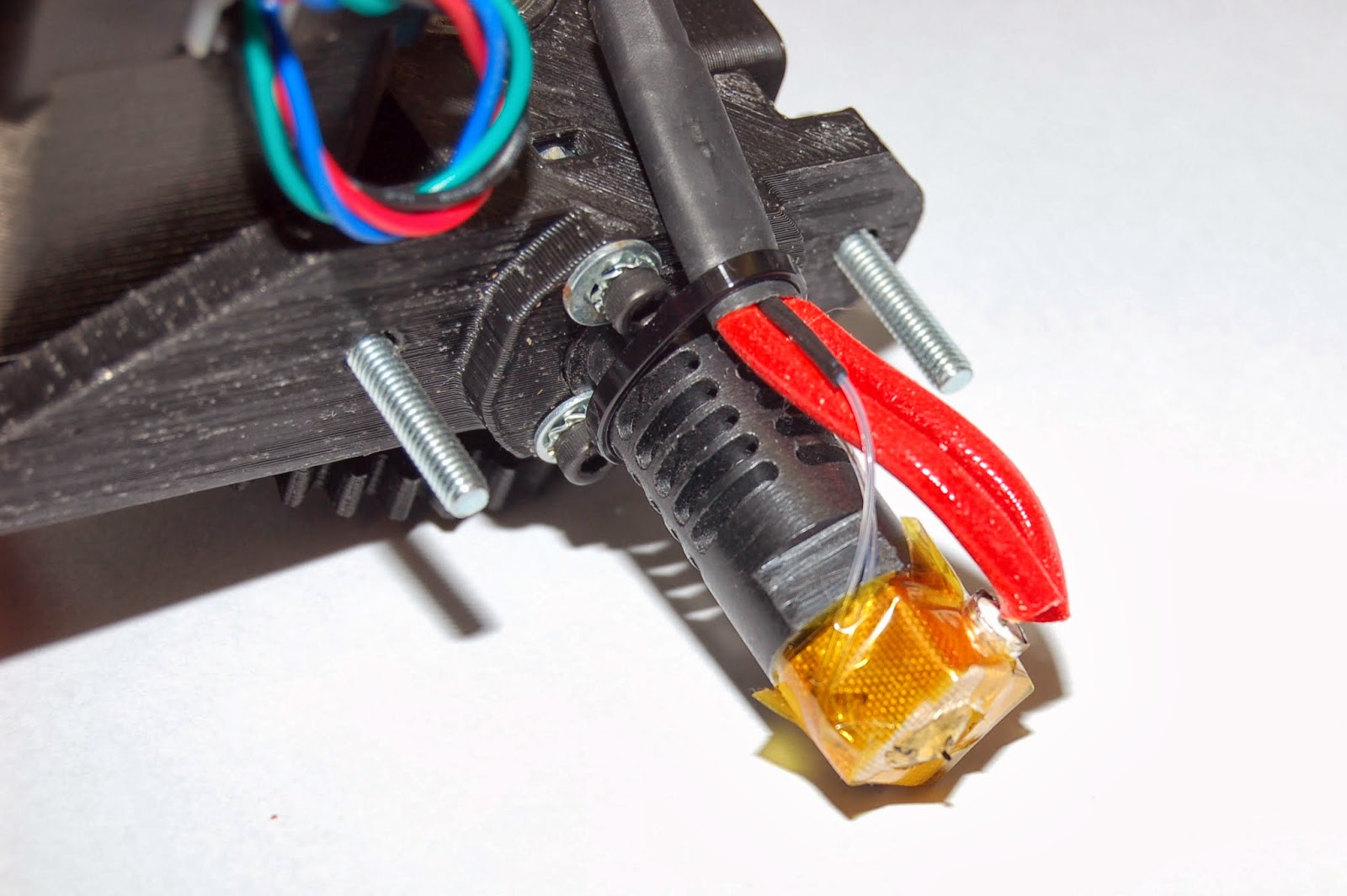
The cartridge heater was a close fit to the hole in the J-Head brass heater block, and with one or two wraps of tinfoil it pushed snugly into place. (Cartridge wrapped in tinfoil and partially fitted, in photo above.)

I fitted the little PTFE sleeves to the thermistor, soldered some wires on and insulated the joints with heat-shrink. I inserted the thermistor into the hole in the heater-block, and surrounded it with some car exhaust putty. The wires from both the thermistor and heater cartridge where then zip-tied to the barrel (photo below.).
I thought about using car exhaust putty to secure the heater also, but the wiring is quite stiff, and it's a good fit to the block so it doesn't seem to be drifting. The one reservation I have about the cartridge arrangement is the bend in the wires. I was careful not to kink the very stiff wires, and hopefully they will be fine since they are secured well to the peek barrel. We'll see how it goes.
The J-Head Nozzle is secured to the extruder with three M3 bolts, M4 washers and M3 star washers to ensure nothing vibrates loose. This is Nophead's design, an excellent method of securing the nozzle. The M4 washers sit against the shoulder of the groove in the PEEK barrel and lock it firmly into the perfectly sized hole in the base of the extruder. It's not going anywhere!

I left the exhaust putty to dry for a few hours, connected the thermistor and heater into my connector board, plugged in my ribbon cable and gave the block a few hours at 100 Deg C to bed dry out the putty completely.


PID Tuning
A purchased printer kit, such as Nophead's Mendel90 will have pre-established PID values in the firmware, which will have been set for the characteristics of the extruder. The purchased M90 kit ships with a power resistor (at time of posting), but since I've chosen to try out a cartridge heater in the J-Head nozzle I've retuned the Marling firmware PID values using an auto-tuning feature. The auto-tuning is called on using an M303 Gcode command which is manually sent to the controller from the host software. If the command is executed on it's own it sets a target temperature of 150 Deg C, but to calibrate for different target temperatures the S parameter is added, e.g. M303 S230. You may want to obtain separate PID values for different target temperatures (different materials). 

Once the PID tuning has completed its process it will return a set of constants for you to note and enter.
The PID values can be later sent via a Start-Gcode, written to EPROM if supported, or hardcoded to the firmware. For hardcoding, the values are entered in the Configuration.h file, the firmware compiled and downloaded to the controller.
e.g.
// J-Head Mk V with cartridge heater. IOS 20131002
    #define  DEFAULT_Kp 27.95
    #define  DEFAULT_Ki 4.22  
    #define  DEFAULT_Kd 46.25

Repetier Host has a convenient temperature plotting capability which illustrates what's happening as the auto-tuning runs. You will see it tuning (pict below) to a target temperature of 220 Dec C, although I later repeated it to a target temperature of 230 for ABS, and at 185 for PLA, noting the value set for each.. The nozzle should be allowed to cool completely before repeating a calibration.

The graph shows the calibration process in action. The power is first applied fully, then as the target temperature is reached it is cut, then applied in cycles, reducing a little each time. The power is shown as % over time in Green, and Temperature plotted in Red. The concluding values and finishing message is also shown in the picture below.

After writing the new PID values to the firmware I set a target temperature and turned the heater on. The graph below nicely illustrates the rate of heating, climbing quickly on full power to well over 200, then PID Control cuts in within 10 Deg of the target, set in this firmware line "#define PID_FUNCTIONAL_RANGE 10",  and from there you see the temperature curve climbing again but quickly smoothing out to the target temperature. Also visible is how the power delivery settles to modulate at a much reduced level, maintaining the target temperature nicely (green graph below.). The red curve drops down when the heater is turned off.
Finally, for comparison purposes I generated the same graph on my older printer, with it's Gen6 Controller, J-Head IV Extruder and 5.6 ohm power resistor. See picture below.
There are a number of aspects to compare, the rate of temperature rise and time to reach target temperature, the draw on power, the quality of PID control. There are explanations for the difference in each comparision, but one major conclusion... my new set-up is significantly better in all respects and I look forward to printing with it!

As always, thanks for viewing!
NumberSix