Pages

Sunday, March 27, 2011

Opto endstops and some other details...

To get the printer to 'home' to a zero x, y and z position the controlling electronics needs some feedback to let it know when it's reached a minimum travel on each axis. I'm using opto endstops to do this. They are mounted in a fixed position, and a 'flag', a little strip of aluminium in my case, is attached to the moving part which is carefully alligned to pass through the opto gate, breaking the beam. The photo below shows my x-axis opto/flag and z-axis opto and flag.


I will probably have to adjust these slightly once I have the extruder in place but it was a good exercise to position these, and check that they were working correctly by exercising the "Home" buttons in the RepSnapper host software. I can now move them to any position and they will return to the same zero xyz position when I hit "Home All" button on the Print Tab in RepSnapper!


Here's the y-axis endstop, at the back of the printer. There's a flag in under the print platform.

The z-motors are wired in parallel in the Prusa design: Two motors turning together, lifting and lowering the x-axis assembly. The simplest way I could find to do this was to wire them into a connector block and run from that to the board. I ran the wiring behind the board just for neatness. This pict shows that arrangment with the white 4-connector block:


On a final note, the z-axis motors needed a little securing but not much so I just strapped them in with a rubber band! The recess in the mounting block stops them rotating.

Thanks for viewing!

Gen6 Electronics connected up!

A satifying milestone was reached this past week. I connected the stepper motors and newly mounted opto endstops to the Generation 6 electronics. There were a few little snags to be overcome to get it singing but singing it is! I've no extruder built yet but I was still able to load a test .stl (beethovan.stl no less, from Thingiverse! None of your 40mm test cubes round here! :-) ) and conduct a virtual print, as a way of exercising each axis! Climbing that learning curve now!!! :-)


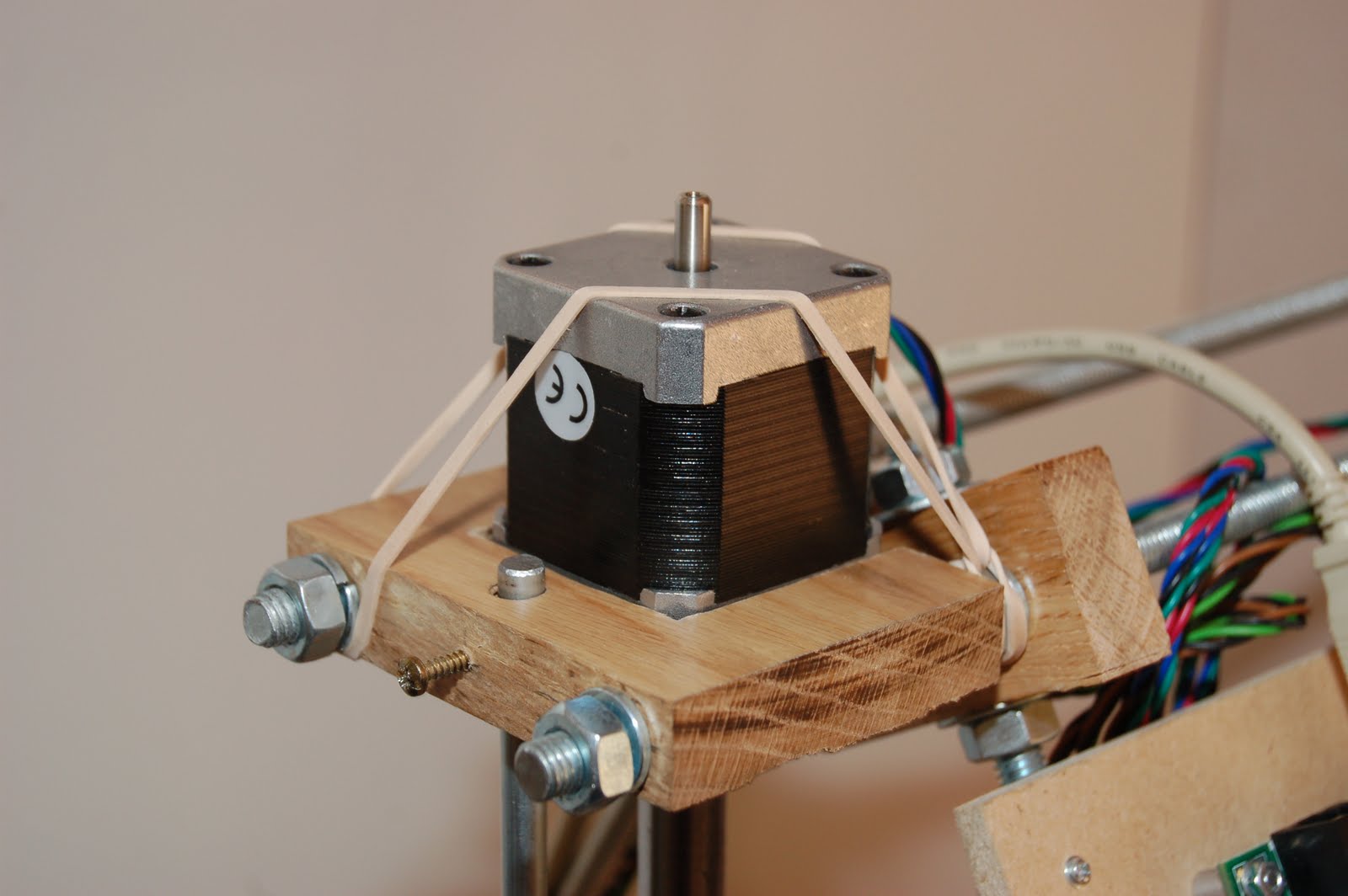
I checked out the basic motor movements first using the manual controls in RepSnapper.
I had to make some changes to motor directions, an opto related setting, and the z-axis steps-per-mm setting. This was all done via the Arduino software, changing the 'FiveD_Gcode_Interpreter' firmware, which I downloaded from the Mendel-Parts.com site.

In the Arduino software open 'FiveD_Gcode_Interperter' firmware. I'd suggest you take a copy as master back-up to save having to download it again, as you make changes to anything in it keep notes in your own version. Anything right of a '//' is a comment.

The following detail will only make sence when you are at this stage of the build. For my machine, a metric Prusa Mendel RepStrap with Gen6 electronics and 'grub pulleys', I now have the following relevant settings in my firmware.
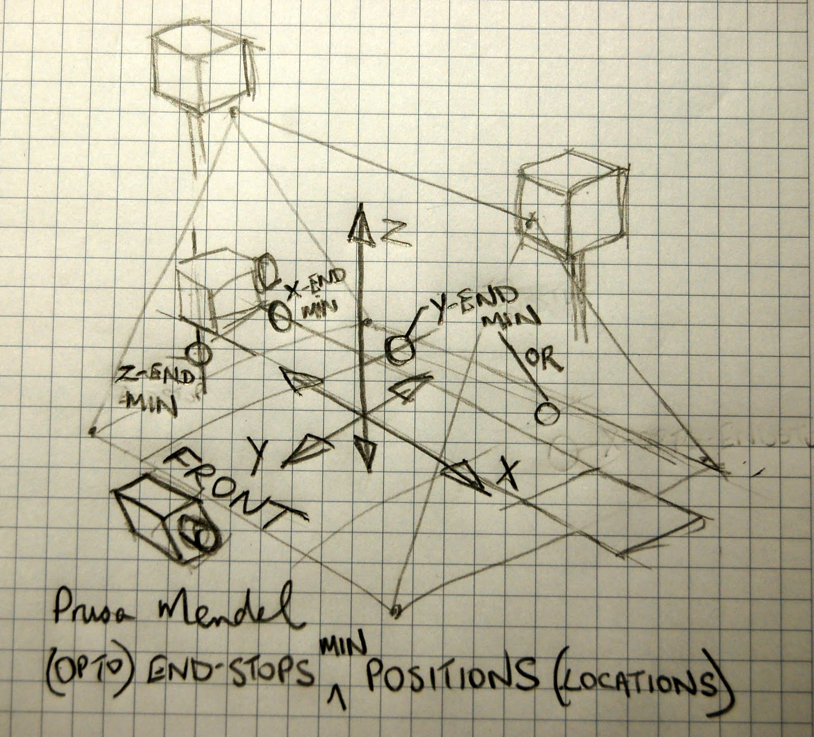
On the 'configuration.h' tab, in the #if MOTHERBOARD == 2 section, I set 'x_endstop_inverting' to false.
               #define X_ENDSTOP_INVERTING false
               #define Y_ENDSTOP_INVERTING false
               #define Z_ENDSTOP_INVERTING false
The setting on 'z_endstop_inverting' is set to 'false' if you have opto end-stops marked 'TCST2103'. They will appear not to work correctly otherwise so worth checking if your optios don't seem to behave on first use.

I had to invert the direction of the X motor. I did this by changing the #define INVERT_X_DIR to a "1". This was under the section #ifdef GRUB_PULLEYS, again on the configuration.h tab.

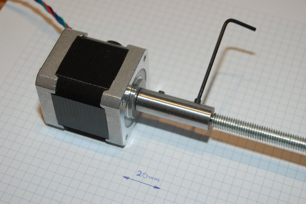
Finally I had to adjust the 'STEPS_PER_MM' setting for the Z-axis. I found that when I clicked on +10(mm) on the manual controls in RepSnapper it was actually climbing about 14mm. To mind what 'steps_per_mm' I needed to set for my M8 threaded rod, I uses Prusa's handy RepRap Calculator. For my machine, with it's Nema 17 motors, 1.8dev motor steps, and microstepping of 1/8 the setting came out at 1280 steps/mm. A practical check is to put a ruler against the Z-axis, hit +10mm in RepSnapper and whatch what happens!

Once you make your changes in the configuration.h tab in the Arduino program, save, select Sketch... Verify/Compile, when that's done select File... Upload to I/O Board.

Note:
In the Arduino software, under Tools... Board... select "Sanguino", or you'll get errors if working with the Gen6 electronics.
Close 'RepSnapper' so it's not trying to talk to the board while you are uploading new firmware. Arduino will tell you when downloading is finished. The 'debug' light will flash quickly while downloading is taking place. When done, press the 'reset' button on the Gen6 board and your new settings will be loaded.

Comments and questions welcome.

Thanks for viewing!


Saturday, March 12, 2011

Beginning to come together...

I now have all the major components, with the exception of the all-important extruder assembly, ready. You'll have seen from previous posts that I completed building the x-axis assembly and mounted the motor and idler pulley. Not having made a decision regarding extrder type yet, I've just made a flat mounting plate (a square of 6mm MDF) which is attached to the 'x-bushings' using some plastic water pipe clips. This allows me to unclip the extruder mounting board when I need to.

I've gone with the high mount position for the electronics (Gen6). I see a double benefit to this. It presents the board where I can see it's status lights and get to the 're-set' button and connections easily (although when set-up I shouldn't need to be changing anything around), and secondly, the mounting board (6mm MDF) adds structural rigidity to the whole printer assembly. The printer isn't loose. In fact it's an amazingly robust construction. A lot of thought has gone into the design, with good use of triangulation. But there is no diagonal bracing in the 'horizontal - lateral' direction. The high-up mounting board for the electronics brings this bracing to the structure. The down side is it reduces visibility to the build platform. A good comprimise might be a 'perspex' piece.

See pict below for a visual on current build status:


You'll notice from the picture that there's a lot more has come together since I last showed a full picture of the printer, but you'll also observe that elements like the end-stops and all the wiring have just been loosely dropped into place. This was to establish good wiring layout and electronics board positioning. There is only the one board which controls the whole unit. That's the benefit of the Gen6 electronics, and I must admit the large mounting board is a bit of an over-kill, but as I've mentioned it's adding structural rigidity.

I was mightily confused about where the end-stops should be placed. (By the way, I got my motors and end stops with end-connectors fitted, so the wiring is of a delivered length -Mendel Parts. It seems to be spot-on. I should be able to hide excess cable length behind the mounting board and not get into cutting to length.) Sorry... back to the end-stop positions: I did a post and a sketch regarding this matter over on the RepRap forum and got great feedback there on where to place the end-stops on each axis.

I believe my sketch illustrates the positioning of the x, y and z end-stops in their min positions for this particular design - 'prusa mendel reprap/repstrap' so I'll reproduce that same sketch below for reference:


As a detailed aside...
I noticed from other posts that the z-axis coupling between the motor and the threaded rod is a common point of failure, where printed couplings are used. I got some help from a friend and had 20mm of the rod ends turned down to 5mm diameter to match the motor shaft diam. I then got a mild-steel bar drilled through with a 5mm hold and two 3mm holes drilled and tapped to take grub-screws to anchor the shaft and rod in place. I filed a small 'flat' on both shafts that the grub-screw tightens against. Here's a picture of that coupling:

That's it for now. The project is suspended for a couple of weeks as I travel for work. Thanks for visiting!

Tuesday, March 1, 2011

X-axis motor mount and idler mount...

With the basic x-axis assembly constructed it was time to figure out how best to mount the motor and idler pully to the assembly. My original basic x-asis ends had not taken this into consideration. It was now time to address this!

I usually start with a dimensioned drawing. I hand draw on grid paper sometimes. It allows me to watch TV at the same time! I've found starting with a drawing gives me a good idea of scale and proportion of the parts, and gives me a plan to work to, saving time and reducing rework. Here's my working drawing:

I continued my desired goal to work with the oak floor board as my construction material, so with my sketch done I adjurned to the garage to break out the power tools! :)


Two pieces were cut, drilled and routed to the desired shape. The routed recess in the left piece was to receive the motor, providing greater support for the motor, while still leaving the full thickness of the board to maintain strenght in the block. Sinking the motor into the block also allowed the shaft to protrude further on the other side. The square block had an 8+mm hole drilled through, and a 20mm hole sunk half way to receive the head of an 8mm carriage bold. I filed out the center to a square shape to receive the square part of the carriage bold shaft. Note: The hole in the 50x50mm block is higher than center, so the base of the idle bearing is aligned with the base of the drive pulley on the stepper motor, allowing the drive belt to run perfectly horizontally.

These pictures (above) show a trial fitting of the stepper motor to it's mounting block, and the idler pulley (skateboard bearing) sandwitched between various washers, all held on by an m8 nylock nut.


Securing the motor mount block to the base was done with two screws from underneath. The idler block, at the far end of the x-axes assembly was also held in the same way, but their allignment was checked before the second pilot hole and screw was fitted to each. (They are assembled dry at the moment, but I'll glue and screw them for a stronger and more perminent assembly at a later point.)

Here (above) are the 'end' and 'motor' mounting blocks, now in position on the x-axis assembly. I was limited in the overhank I could achieve for the belt because of my assembly technique (the two screws from underneath). This may impact on my extruder design, but I'm not worried at the moment... haven't got to that yet! :-)

And finally, for this post... the completed x-axis assembly!


Thanks for visiting.