Pages

Sunday, December 30, 2012

Earbud holder with keyring tab...


The Earbud Holder from Thingiverse caught my attention recently. There was a comment asking if it could have a key chain loop added... it sure can! It's a matter of personal preference whether you print the version with or without the keyring tab, or take the design further. It's great how designs evolve.
 I fitted a small ring and short length of cord to the holder.

Notes:
I dropped the original Core .stl into Sketchup and drew on a tab with a hole in it, to which you could fit a keyring. I then took the evolving cover design from here: http://www.thingiverse.com/thing:38292 and put a notch in each cover so it would still close around the new keyring tab.
I then exported the new .stl files and ran them through Netfabb Cloud Service . It always does a good job of cleaning up the stl. They were now ready for printing... ABS, 50mm/sec, .4mm nozzle, .3mm width /.45mm height.


My first set of covers cracked as I tried to clip them on to the core. They broke along the print lines. On examination it was evident there was poor bonding between layers. I've been pushing the speed in recent times and at this point I expect the plastic just wasn't hot enough for the speed (230Deg C at 50mm/sec).

I increased the temperature to 245 Deg C. and reprinted just the two covers. Now, you know you should never change more than one parameter when troubleshooting, but I couldn't resist altering the layer height/width also, to increase the horizontal resolution and give a better fit between the parts. The covers were reprinted at .25mm height/.375mm width, 70mm/sec. 245 Dec C.

I've uploaded the modified design to Thingiverse: http://www.thingiverse.com/thing:39767

Enjoy!
NumberSix

Wednesday, December 26, 2012

A focus on ABS and a new printer hood (with video clips)

ABS is a tough, impact and temperature resistant plastic. It can be injection moulded and extruded. It has many common uses, from Lego to car bumpers. Being able to print in ABS is an important progression for me in terms of the robustness of the objects I might design, prototype and print.

My first ventures into printing with ABS did present some challenges. It's extrusion temperature, in the region of  240 Deg C, is a good deal higher than PLA (185 Deg C). The rising heat from the hot end to my PLA x-carriage was a first concern but the use of an un-ducted fan to cool the underside proved problematic. The freshly extruded ABS was very sensitive to the cooling airflow, causing poor adhesion of the first layer to the print bed. If' you've only printed in PLA you'll find PLA prints better with some cooling, preventing curling, but the first layer of ABS is far more sensitive and does not like stray cooling at all. Fitting a ducting to the fan (light green part visible in photo below) focuses the air flow across the J-head insulator, also keeping the underside of the x-carriage cool. I may eventually print an x-carriage in ABS for peace of mind.

The big addition to my set-up is the hood (see photo). It's a simple box construction made of 6mm MDF and light timber frame. The front has a clear acrylic panel. 

The purpose of the hood is to maintain a steady raised temperature around the printer. I found it levels out at around 28 Deg C at the moment. The printer is located in the garage with a frequently used large door, so heating the whole area isn't practical, and in the winter time the printer extruder and heated bed struggle to get to a working temperature without the hood. The addition of the hood has made a great difference to temperature management in our colder winter months (Ireland). With the hood externally vented it has also eliminated minor concerns about any fumes the ABS might give off if over heated, although I've had to control airflow through the vent to reduce air loss from hot-air convection through that pipe.

Next item to get right for ABS is the heated print bed. PLA is happy with a heated bed in the region of 60 Deg C temperature, and with some PVA coating on the glass bed it will stick well. ABS is a different story. Experimenting by many has resulted with varying guidelines on what temperature is best for the heated bed under an ABS printed part. People seem to have had good success with temperatures ranging from 80 Deg C to 120 Deg C or even higher. This higher heated bed temperature for ABS is required for good initial adhesion and preventing warping as the object grows, but you should reduce the bed temperature after the first layer to prevent wall shrinkage at the base of printed parts. The use of PET tape or ABS juice (ABS/acetone solution) is also found to help adhesion. Some people just ensure the glass is cleaned thoroughly and get very good adhesion straight to glass.

The quickest and easiest way to give a guided tour of my current printer set-up is to post a short video. In it you will see the first layer of the Santa Sleigh being printed. It's being printed with 3mm ABS filament, with a .5mm nozzle at an initial temperature of 240 Deg C, bed temperature of  115 Deg C (approx). First layer is printed slowly but it picks up to about 50mm/s later.

As I move the camera around you will see the host software I'm currently using "Repetier-Host", my wall mounted spools, and the printer electronics, which are now moved outside the box (they need a cover!). Finally, for the keen eye, you will see some timber cross-bracing across the rear threaded rods of the printer. This has enhanced the stability of the unit immensely. My z-rods hang freely from the motors unconstrained. I only use a single trapped z-nut on these rods in each x-end, and no backlash springs.

This video clip shows the Santa Sleigh being printed a few layers in (.3mm height/.45width, 25% fill). I've a temporary temperature probe under the heated bed which shows a reading of about 117 Deg C. I expect the surface temperature of the printer bed is a good 15/20 Deg C less. My bed temperature is controlled via a simple circuit (see here). The temperature is set with a variable pot dial. I've various marks on the dial for PLA, ABS first layer and ABS. It's all a bit experimental, but works.


This short video shows the printing of the Sleigh, utilising a time-lapse shot every 20 sec, and a look around the finished item at the end. The printer bed is 200mm x 200mm so you can judge the size of the printed object from that.

Finally for now, here's a clip of the Reindeer being printed. All eight in one go, along with the support struts.

Concluding notes:

  • Printing with ABS has greater temperature management challenges, for both the hot-end and printer bed.
  • The single biggest tip I can give is to reduce the printer bed temperature immediately after printing the first layer of any ABS job. This will prevent shrinkage or distortion of the lower 5mm of the object, a phenomena dubbed 'elephant feet' on the forum, because of the inward deformation of the work around the base. I estimate a reduction in bed temperature of about 20 Deg C is not unreasonable, but I would recommend you experiment to find settings that work best for your own set-up.
  • I've not found ABS parts to be as dimensionally accurate as the same parts printed in PLA. I believe this phenomenon is down to ABS shrinkage. You may want to allow for this in design.
  • The finished ABS product has a smoother feel and any blips or minor stringing is much more easily removed than equivalent imperfections in PLA.
  • While the print resolution is the same, ABS seems to look a lot smoother.
If you have any questions or comments regarding the set-up or operation of my printer feel free to post a comment of contact me via the RepRap forum (http://forums.reprap.org).

Thanks for viewing!

NumberSix.

Monday, December 24, 2012

Christmas printing fun...

Thingiverse Santa Sleigh driven by the Snowman! Some red acrylic paint easily added a touch of colour to the white ABS plastic.

A variety of other Thingiverse Christmas ornaments!

The Angel was creating by tracing some internet clip-art in Sketchup, extruding the shape a few mm and cutting slots so the two halves slide together. It's a simple construction but looks well.


Merry Christmas and a Happy New Year to all!


Sunday, October 7, 2012

Printing a clock...

I've always had an interest in clocks. They can be hypnotic and fascinating, masterpieces of mechanical engineering, and things of beauty. But could a clock be printed on a home 3d printer? Would it work? I was delighted to see a clock published to Thingiverse (The Makerbot clock) but was disappointed to learn that the hardware kit was no longer available. That didn't deter me.

The finished item is a simple and pleasing open style, weight driven, wall clock with a 9" face and 3ft pendulum.

It was a printing challenge and will test the accuracy of any printer. For the most part the gears came out cleanly and meshed well with each other when the clock was mocked-up. Some test assembly and hand turning highlighted a few sticky points. They where easily sorted with a needle file. I printed using my .5mm nozzle but in hindsight a .35mm nozzle would have resulted is better meshing gears and post print tuning/filing.

The range of parts can be seen in the above photo. If you study the MakerBot assembly instructions you can get an idea of the hardware required, but I had to deviate from the original bill of materials in a number of items. I could only source the tubes that drive the hands in metric dimensions so I had to alter the hole sizes in some of the printed parts to match my brass tubes. I sourced the little bearings on ebay. They were inexpensive and came in a packet of 10. The pendulum shaft and second-hand shaft are welding rods. The weights are filled with 2 Cent coins (Euro). The original design suggested a 1 Cent US coin. They are the same size.


To give added strength and enable wall-mounting I cut a circular backing board from some 15mm chipboard, and mounted the clock base plate to that. I used longer bolts than specified and allowed them to travel right into the backing board for extra rigidity in the assembly. The upper frames were quite light and didn't hold the gears quite as well as I would have liked.


Modifying the mechanism
When I first started the clock it was running too fast. The published escapement wheel has 15 teeth. That results is the second hand advancing by two second increments for each pendulum swing. But combined with a 1 meter pendulum, the second hand completes a full revolution in only 30 seconds. That said, I expect this clock was only ever published as a printing show piece and for it to tick/tock away in any fashion could be considered a success!

On examination of the SketchUp file included in the Thingiverse publication I found an alternative escapement wheel which had 30 teeth, allowing a more refined movement of the second hand. The escapement paddles also need adjustment to fit this wheel. (For anyone that really want's to get into the detail I found a good publication on excapement mechanics here: www.abbeyclock.com/EscMechanics.pdf )
That article is a bit over involved for this purpose but does show you how to draw paddles that are a good fit for the escapement wheel.


I exported my newly shaped paddles to .stl, then printed and fitted the two new parts.

The finished clock
The clock is probably as good as I'm going to get it now, for a home printed plastic clock it's pretty amazing! It will only run for a few hours on a single wind so don't expect it to replace your kitchen clock any time soon. I've provided a little video clip below so you can see and hear it in action!


Thanks for viewing!
NumberSix

Sunday, September 9, 2012

Bridging gaps (video clip included)...

Once your machine is printing well there are always new challenges to be overcome! I was printing some Mendel90 parts this past week and found some of the parts needed bridging, e.g. the bar clamps:  http://www.thingiverse.com/image:110664 , not to mention the x-motor-bracket:  http://www.thingiverse.com/image:110722

There are many bridging calibration test pieces out there and I was inspired by the thingiverse hollow cube and quickly drew up my own 30mm cube in Sketchup and printed it as my calibration piece. It makes a nice 'give-away' printed object!


Technical note: I printed it at .3mm height, .45mm width, slow speed. I'm currently using Slic3r 0.9.1 from within Repetier-Host (v0.70b). I'm happier specifying both height and width in Slic3r at the moment for what it's worth, following Nopheads guideline 1.5 ratio (.3mm *1.5 = .45mm).

The bridging works best for me when I set a Bridge Flow Ratio of .9 (in Slic3r... Print Settings... Advanced). That supplies less plastic than would normally be laid down for the given distance, therefore stretching the plastic across the gap. As the plastic cools it also tightens up, pulling straight. This can be helped by a fan blowing cold air at this point of the print.

I'm using 3mm PLA with a .5mm nozzle, printing at 185C (195C first layer). The only cooling going on is any air drifting to the work from the x-carriage mounted fan that cools the hot-end insulator (peek part of the j-head).

I captured the bridging moment on video for people to see bridging in action! Also visible in the opening minute is my new y-carriage, PCB heated bed and the ribbon cable connected beneath it, for power and thermistor. I thought that might be of general interest also.


Thanks for viewing!


Sunday, September 2, 2012

Heated bed with three point leveling...

This recent collection of improvements to my printer stemmed from a desire to try some ABS printing, which I haven't actually got to yet. Again a case of one thing leading to another... It needs a higher heated bed temperature (110deg C I believe), and my resistor heated-bed just couldn't achieve those temperatures.

I'm a fan of the three bearing y-carriage. I converted my y-carriage to a three bearing rig a while back (here), but the print bed (upper plate) was still leveled by adjusting four spring loaded screws. When Tony at Think3DPrint3D did a version of the PCB heatedbed that had a support hole in the middle of one edge (see here) I just had to try out an arrangement that had three bearings and only three levelling screws for the print bed.

A heated bed with only three support points would need a support plate that was as large as the bed, but a lot of that support plate would be redundant. I felt it was also best if these three support points were positioned over the bearings for maximum support. The resulting layout eliminates the smaller lower plate in typical Mendel y-carriage designs, but does mean that the y-rods need to be raised to the upper position as the printbed overshoots either end to achieve a full 200mm print area in a Y direction.

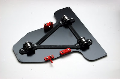
This is the new Y-carriage I built:

The carriage is made from 3mm composite sheet material, commonly known as DiBond. It's a plastic sandwich between two light sheets of aluminium. It's very strong and very light. I happened to find some in a black finish. This plate acts as both the mounting board for the bearings and the support board for the heated bed. This simplifies the construction and overall weight of the y-carriage. I used bearing mounts that have been joined by a simple triangle to position them (http://www.thingiverse.com/thing:19771). There's a huge variety of y-carriage bearing holders on thingiverse, some have integrated belt clamps, some without. I just transferred my existing belt clamp and tensioner, and my opto-endstop flag.

The composite sheet material was marked out and cut with a jigsaw, using a fine toothed blade. All the holes were carefully marked and drilled. The three holes to support the heated bed were taped to take M3 bolts, to allow a Nophead style mounting and adjusting method which he talks about here. I also adopted the insulation and cabling method he describes and utilises on his Mendel90 printer. 

Wiring the heated bed: 

The version MK2a (note the 'a') of the PCB Heatedbed has larger soldering tabs as well as the middle hole. Given I wanted to position the middle hole over the single bearing it meant my ribbon cable needed to take a 90Deg turn to position the loop it in the direction of bed movement. The photo above also shows how I soldered on the ribbon cable and attached the thermistor. The exposed contacts were covered with some tape to prevent shorting on the foil insulation which will sit beneath.

I cut a piece of corrugated cardboard and glued on some kitched foil to make an insulator for under the heatedbed.

The foil faced cardboard sits between the carriage and the PCB heatedbed. To secure the ribbon cable I cut a piece pvc tube to protect the ribbon cable from the edges when I used a small buldog clip to clamp it in place. See photo below.
(note the adjustment screw above was not what I settled on.)

The adjustment screws were made up as follows. I took a long M3 spacer nut, thread-locked a headless screw into one end, and cut a screw to fit the other end. (I use a small disc in a Dremel to cut bolts/screws to length.)

I wanted 'soft' washers to pad the lock-screw. The corner of the PCB is quite delicate and I suspect easily broken. To make some PTFE washers, I pushed some PTFE tube through a hole in scrap piece of wood, and used a sharp chisel to cut as many washers as I needed.

Below is a photo of the adjuster screw/nut  It works by loosening the top lock-screw, then turning the long nut to raise or lower the board, then tightening the lock-screw when done.


Here's the newly assembled y-carriage and PCB Heated bed. I cut a piece of picture frame glass to size for initial trials with PLA. I may have to get something better for ABS. There's a bit more work to do before I start into ABS. I want to build a hood and extractor next.


Conclusions:
The bed levelling process is so much easier with only three height adjusters. Start on the right, level front and back, then move to the left centre screw and adjust it until until the bed is levelled in a left/right direction. I level off the print-head tip, and perform the exercise with motors off moving x and y carriages by hand.

Raising the y-smooth rods to their top position only results is a small loss in z-height because the new layout has one less support plate. The original smaller board/plate that held the bearings is no longer required.

The use of Triffid_hunter's bar clamps allowed the rods to sit on the threaded rod, giving a print bed that was almost level before any adjustment. The amount of final adjustment needed with this construction is extremely little.

The whole assembly is much lighter than my previous one. The loss of one board and the introduction of the composite sheet material has contributed to this. The net benefit of a lighter y-carriage assembly is greater print speeds with less strain on the motors or less risk of skipping due to inertia.

That's all for now. Thanks for viewing!
NumberSix 

Sunday, July 22, 2012

Turk's Head print...

The Turk's Head print came out so nicely I thought I'd give it a little space of it's own. It might even make a novel Scout woggle, but you might want to use the version without a base and take on the challenge of a supported print!

I printed it in PLA at .3mm layer height with a .45mm width and 20% infill. It was set to a perimeter speed of 30mm/sec and left to chug away while I walked the dog.

What I have observed when printing in black PLA is that the final finish can change from gloss to matt depending on whether you have a cooling fan on it or not, but also depending on the print temperature. This item has more of a matt finish. I dropped the print temperature down from 185Deg C to 183Deg C as I observed the initial few layers looking a bit 'soft' and shiny. On my current config there is a bit of downward air flow from the x-carriage mounted fan and this seems to serve well as a work cooling fan as the print head moves about.

While the print resolution could be considered quite coarse by current standards, there is forgiveness of the surface finish as you eye seems to be tricked into thinking it is a woven cord or rope type material. It's a nice object to print. I'll probably reprint it once I get some white PLA. Would probably look better in white.

Y-carriage changes...

I've recently changed the number of linear bearings (LM8UUs) under my y-carriage, reducing the count from four to three. While my y-carriage was running smoothly enough I could detect slight binding on either end of the travel and I couldn't get rid of it no matter how much tweaking I did to the positions of the four bearing mounts. My suspicion was down to slight irregularities or even minor bows in the rods. I'm sure precision ground rods would be a better solution, but I figured moving to a tripod bearing arrangement was worth a go.


I drilled new mounting holes in the middle of the left side and moved one bearing bracket to the middle-left position. I kept two bearings to the side closest to the belt to minimise any turning motion the belt might introduce with less alignment constraint on one side. The base plate looks like a piece of Swiss Cheese at this stage with various experimental reworks, but you should be able to make out the new bearing mount positions in the photo above. A smaller change I've also made is the reversal of the y-belt at the idler end (far side), to give a smoother belt surface contact with the far idler bearing(s).

With the most firm supports for the heated bed and top plate now in a triangular shape I felt the next step was to reduce the spring loaded adjustable supports to three also. I've always felt that levelling the print bed would be a lot easier with three points of adjustment rather than four, and this was an ideal opportunity to explore that design. You can see a new hole in the centre left edge of base plate to take the spring loaded levelling bolt.

Manual movement of the y-carriage was much smoother through the entire travel length, a full 200mm distance. My only final compromise was to not completely tighten the bolts on the left bearing bracket, allowing it some minor horizontal play. I think it may be best to replace that 'smooth' rod eventually as it seems to have some imperfections.

Levelling the print bed:
Levelling the bed was a dawdle! Now with only three adjustment points it took no time at all to get it level. I started on the right hand side where there are two adjustment screws, positioned the print head to the right and manually moved the y-carriage back and forth adjusting the right screws until the bed was level. I then moved the print head manually left and right, adjusting the left bed adjuster until the bed was completely level. I did this first pass levelling visually with the print head about 5mm from the bed. I lowered the print head and repeated the process to fine-tune the levelling.

Print bed levelling was made even easier with these 'trapped nut' thumb wheels, visible in photo above.


Conclusion: In the case of y-carriage bearings and print bed levelling, three points of contact is as good if not better than four. The only proviso is that you have a sufficiently ridgid print bed plate, so that it doesn't droop in the unsupported corners.


The movement of the y-axis feels, and even sounds smoother with only three bearings. It may be a better compromise solutions if you are using rolled stainless smooth rods as against precision ground rods.


My current config:
To show the new y-carriage in action, and to give a general overview of my current configuration here's a short video clip. It's printing the Turks Head from Thingiverse.

It's still a Mendel Prusa layout, with my wooden Vertexes(?) and z-motor mounts remaining on from my original fully wooden construction. I've a mix-up of x-ends but plan to upgrade those shortly. I've a Greg's Wade Reloaded extruder and a j-head IV 3mm hot-end with a .5mm nozzle. I've a 'four resistor' heated bed which is thermistor controlled but the temperature manually set via a pot.

Thanks for viewing. Now I'm back to printing! :)


Tuesday, July 17, 2012

60mm fan holder for Gen6 cooling...

Quick Post: It's good to keep the electronics cool. I salvaged a lovely quiet 60mm fan recently so I printed off a holder from thingiverse for it (http://www.thingiverse.com/thing:13469). I modified the base plate of the holder so it clipped on to the printers threaded rods. See photos...
There was a bit of stray airflow on to my printed bed, so I slotted a clear plastic lid behind the board to stop unmanaged airflow to the bed. I'll also need to fit a fan-guard to the fan. I'm happy to leave it as an open sided arrangement for now.
Here's a view of the reverse side. I simply took the base plate from thingiverse into Sketchup, added a tab at  the top, rounded the corners and repositioned the push-on rod mountings.

Cooool! :-)

Sunday, July 15, 2012

More extruder talk...

There's such a variety of RepRap part designs out there that you really have to match them up carefully if you plan to upgrade any individual aspect of your printer. You can 'pick 'n' mix' but as I've learned you should think it through and double check everything before starting in to an upgrade. Here are some examples of the minor issues I bumped into when I bought a new extruder hot-end, the J-Head IV-B.
The j-head has a 16mm diameter insulator (the black PEEK cylinder). You have to find some way to mount the insulator to the extruder body. There are many options. There are various mounting plates available to fit the notch, and then bolt the plate under the extruder, but the top of the insulator must still insert into the extruder. My existing extruder only had a 12mm hole in it's base, so I had to print a new extruder. I had a look around and decided I'd try this extruder (Jonas Kuehling's version of Greg's Wade extruder). Jonas has a variant with a 16mm hole in the base, and holes to bolt across the insulator notch.

By the way, RichRap also supports the lower end of the j-head with a modified bracket. You can review that here: http://richrap.blogspot.ie/2012/03/mendelmax-quick-fit-x-and-quick-fit.html (scroll way down in his post to the Extruder section.)

So I had to print a new extruder. To save effort (so I thought!) I'd transfer the hobbed bolt and recently printed herringbone gears from the extruder I was removing, but I soon found more complications. The combination of Triffid_Hunter's Herringbone Gears, my hobbed bolt and Jonas' extruder just wouldn't line up. The hobbed notch wouldn't align with the filament guide hole and there was not enough travel for the motor to close the small gear fully against the large gear! I should have just reassembled the old extruder at that point and printed Jonas' gear set that did match, but no, nothing like a challenge! :) A second printer would be handy!

I reversed the hobbed bold and put the nut and a lock-nut on the large gear side allowing adjustment and perfect alignment of the hobbed bolt to the filament. I fitted a spring on the other side to keep some tension on the bolt. Between the filament in the notch and the meshing herringbone gears there is actually little incentive for the hobbed bolt to drift horizontally anyway. Here's a photo or two of the current hobbed bolt arrangement! It's been running like this for a few weeks without issue.

Securing the hot-end insulator: The insulator pushes into the extruder base and a common way of securing it seems to be with two M3 bolts through the holes in the extruder and across the notch in the insulator. You may have to pre-drill, glancing the insulator notch to get those bolts to fit. I'm not familiar with the mechanical properties of PEEK. It feels extremely hard and tough. I figured a 3mm drill meeting it at an acute angle would just bend away into the plastic so I took an alternative approach to securing it. I made a simple pin from coat-hanger wire, rounded the tops with a small file and pushed it in with a small clamp (photo below).


It's a tight fit and hold the insulter amazing well. There's no movement in the hot-end. I'm printing for weeks with this securing method and the hot-end/insulator remains securely attached.

I added a little bit of PVC tube to the pin to gently secure the wires rising from the hot-end. The pin can be removed with a wire hook and a firm pull.

Oh... the poorly meshing gears due to mismatch of gears and extruder... I elongated the motor mounting slots with a round needle file and motor now travels close enough for the gears to mesh perfectly. Not idle, but it works!

BTW - here's a photo of all the components that went in to the new extruder.


General comment on extruders: Once you have your printer running smoothly, there is little enough call for the quick-release mechanism on the idler-bearing, and indeed if you've clogged up the hobbed bolt badly the best way to clean it is to remove the bolt. Also, some have felt the need, including me, that a top filament guide is necessary in the design, leading to the return of a top guide.
This brings me to the argument that Nophead presents for the Wade's style extruder. If you use a spring in conjunction with a regular nut on the hobbed bolt then the nut won't loosen, but can easily be removed if you need to inspect or clear the hobbing. Also, if you have got your idler spring tension just right, the last thing you want to be doing is backing the bolts off to remove the idler. If you aren't removing the idler, then four securing bolts makes little odds over two bolts and a hinge, and in some ways makes for a more evenly pressured idler.


I printed it out (photo above) and will fit it out and try it at some point. (I've thickened the base so I can fit a larger gear and have it clear the x-carriage. An interesting side-effect of thickening the base is it gives even more robust support to the 16mm diam insulator, but I would caution that you need significant active cooling on the hot-end insulator if you are going to mount it directly in to a PLA extruder. Another clever touch to Nophead's variant is a circular recess at the inner most end of the 16mm hole. This allows the insulator to seat perfectly into the extruder base without any clean-up of the hole. (You'd have to be there to appreciate that detail fully! :) )

Since I'm on 'extruders' I'd also like to highlight this set of RepRap design reworks by the guys at EckerTech, which includes an interesting take on the extruder. Their extruder design features, hinged idler with no hinge bolt, a single compression bolt on the idler with no spring (good argument for using a washer presented), and a motor that rotates about one mounting point to adjust rather than sliding! Nice work, and they mention in their forum that they plan to publish their designs once they are finished tidying them up. Nice work.

As always, thanks for viewing. Comments and questions welcome!
Regards,
NumberSix


Sunday, July 8, 2012

PVA coated print bed experiment

There was a recent suggestion on the forum from Enlightx that a coating of diluted PVA (50:50), painted on to the print bed would aid adhesion of the printed object, preventing warping or even breakaway. The suggestion was echoed and tried by Rich on his blog. I gave it a go, diluting to a ratio of 1:8. At this point I've been using it for over a week, printing each evening. Here's some feedback on the experiment.


It brushes on easily and dries to a foggy finish. I left it overnight, then put it back on the printer. You could probably paint it directly while on your printer and dry it with your heated bed.

I printed my first few pieces to this newly coated surface with what I now think was too low a layer height, causing it to bond too well to the surface. As the week went on I got more brave and raised the first layer height until it was just a light touch to the surface. Here's a short video that shows how well the printed piece adheres to the newly coated surface.  Even when cold I had to apply some significant force to remove the piece.

You can see the fogged mirror surface in this photo below, and an object that printed without budging. I printed many objects for the week, large and small, and there was no warping what so ever.

The underside shows no ill effects from the PVA (photo below). The first layer infill seems to loop slightly short of the perimeter in the photo. It looks fine in solid layers further up the print. I may have set the first layer too high in this case, preventing the first layer squeezing out to the perimeter.


Conclusion: The dilute PVA coating has a positive effect on print bonding to the print bed. I'd recommend starting with a more dilute solution, perhaps 1:20, and add more coats if that doesn't improve bonding.

If you have been in the habit of running a very low first layer then you can certainly back that off. Too low a first layer will result in the piece being very difficult to remove from the print bed (as in my short video).

Be careful when tugging pieces from the glass as the glass could crack rather than the piece give way.

The shadow of previously printed pieces remains in the PVA coating. It will be interesting to see if this impacts on the finish surface of subsequent prints.

Finally, it will be interesting to see if the adhesion benefit will diminish significantly over time. If it does then it seems that a fresh coat of dilute PVA would be cheap and easy to re-apply.

Thanks for viewing!
NumberSix

Monday, July 2, 2012

The Hot-end...

The majority of extruder hot-ends on the market at the moment come as kits of varying degrees. There's a certain amount of assembly you have to do yourself, but this is changing rapidly, and not too soon I think.

(J-Head IV-b shown above.)

It comes with a resistor and thermistor but they are not fitted. Fitting them is 'fun' the first few times, but after a while becomes a bit tedious. I can see the expanding market moving to some level of pre-assembly, as I can see the broader user population more willing to pay a premium for pre-assembled units and less interested in this doing this it themselves. Even for the enthusiast the process of gathering the heat resistant wiring and appropriate connectors is a bit of a chore and added cost. Another reason I'd favour pre assembly is the 'quality assurance' and consistency that would come from pre-assembled hot-end, which might include some level of thermal bedding-in and testing of the resistor/thermistor. These steps would certainly be worth the little extra, as well as the time saved.

[ J-Head heater block and integrated nozzle shown in picture. The advantage of this design is it's an all-in-one unit and can't leak. You have no worries about tightening on nozzles or loose fitting heater blocks needing lock nuts. the disadvantage is you can't just easily swap out the nozzle to change to a different orifice size. ]

There are many instructional sequences showing the assembly of the hot-end but I thought the process and sequence I've adopted might be worth sharing. I always like to insulate the heater block and have some photos showing that process also below.

Tip: I remove the pin from a small pop-rivet, snip it's head off, and use it as a joiner. I don't solder this joint as solder may melt. I use a PTFE lined, braided wire sleeve on the resistor. I salvaged the wire from an old iron. It's designed for high temperatures!

The resistor that comes with the J-head is 5.6 ohms. With a 12v supply, I've found this gives a very nice heating time and seems well able to keep the block hot in comparison to the 6.8 ohm resistor, also popular in the market. The 5.6 ohm resistor also has a more cylindrical shape and is a snug fit to the brass block. The other resistors (6.8 ohm, Green in colour) I've bough were slightly lozenge in shape and not a good fit. 

This photos shows wires attached either side of the resistor. The choice of colours has no significance.

The tiny little 100k glass thermistor needs it's wires kept apart. I've tried the ptfe sleeve idea on one of the wires, but I've found this bulky. The extension wires are soldered and the joints head-shrinked. Be sure to scrape the wires bare first. They are slightly coated.

What I've found as a better way to keep the thermistor wires apart is to sandwich them between some high-temperature tape (above photo).

The thermistor is inserted into the hole in the brass block and the wires wrapped around the corner of the block, curved around more so than bent at a sharp angle. The tape holds it somewhat, but the addition of the other insulation jacket will hold it in place very well. I don't bother with any fire cement or silicone. It's a personal preference. Also note all joints are heat-shrink wrapped at this stage. The resistor gets removed one last time to fit the insulation jacket.

I use a very light sheet of ptfe to warp the brass heater-block. The material is rated to 280Deg C, and is commonly used as baking tray or oven liner. Wrapping the heater block in this material is more an art form than a science. You may be able to make out the folds and cuts I make in the sheet from the photos.

Once I'm happy that everything is fitting nicely I tape everything down with kapton tape.

And there it is, snug as a bug!

This jacket keeps the heat in allowing faster heat times, and means less work for the resistor to maintain a given temperature. It also protects the heat-block from the negative effects of stray fan air currents. Finally it reduces radiating heat from the heat-block to the newly printed job below it.

One final step is to cut out the holes for the resistor after the jacket is fitted. Mind your fingers!

With the hole cut out, I used a bar through the hole, and small wrench on the insulator notch to tighten home the head into the insulator. It's hard to describe how tight this should be. It's a 'good hand tight'. It came pre-assembled, so I actually marked the joint with a dab of Tippex before taking it apart. I reassembled until the two white marks realigned!

I've more extruder related photos to post but out of time for now. Thanks for viewing!
NumberSix