Pages

Showing posts with label PLA. Show all posts

Sunday, October 13, 2013

Halloween printing fun begins!

The Halloween printing fun has begun... I hope everyone has enough orange and black! There's a great range of bits 'n' pieces out there to print or you can always draw up something of your own. I've started with a Pumpkin. This one from Thingiverse http://www.thingiverse.com/thing:134066

As I ramp up the challenges for my M90, this print tested it well. The Pumpkin is hollow inside, and top closes right in. It actually printed without support to my amazement. There was a bit of spaghetti on the underside of the roof but that wasn't an issue for this object.

Just to set off the Pumpkin, and lower the position of the LED Tealight I drew up a base in Sketchup.

For the finishing touch I put three stick-on feet on the base!

Tech Notes: 3mm PLA, .5mm nozzle. Pumpkin printed with .25 layer height, 2 perimeters, 50% infill. Speed set to 40mm/sec. Small brim and first layer at reduced speed. Temperature 185Deg C, Heated Bed at 70 Deg C. Glass with PVA solution coating. I had no warping or lifting. Clicked right off when cold.

The black base was printed at .3mm layer height and 50mm/sec. 10% hex infill. I'd slow down the top surfaces and increase the number of layers on the top surfaces if using hex infiill in future. It was slightly gapped in places as it tried to bridge a 10% hex infill.

Both parts were sliced with Slic3r. Cooling was enabled under the Filament Settings (defaults used). I have a cooling fan with variable speed on the M90. Detail on it's set-up in a previous post... here. I think it's helping greatly with PLA print quality.

I printed at about 60% of published size as a first run of this. I think the M90 could easily handle it at 100% size.

Happy printing!
NumberSix  

Sunday, September 2, 2012

Heated bed with three point leveling...

This recent collection of improvements to my printer stemmed from a desire to try some ABS printing, which I haven't actually got to yet. Again a case of one thing leading to another... It needs a higher heated bed temperature (110deg C I believe), and my resistor heated-bed just couldn't achieve those temperatures.

I'm a fan of the three bearing y-carriage. I converted my y-carriage to a three bearing rig a while back (here), but the print bed (upper plate) was still leveled by adjusting four spring loaded screws. When Tony at Think3DPrint3D did a version of the PCB heatedbed that had a support hole in the middle of one edge (see here) I just had to try out an arrangement that had three bearings and only three levelling screws for the print bed.

A heated bed with only three support points would need a support plate that was as large as the bed, but a lot of that support plate would be redundant. I felt it was also best if these three support points were positioned over the bearings for maximum support. The resulting layout eliminates the smaller lower plate in typical Mendel y-carriage designs, but does mean that the y-rods need to be raised to the upper position as the printbed overshoots either end to achieve a full 200mm print area in a Y direction.

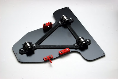
This is the new Y-carriage I built:

The carriage is made from 3mm composite sheet material, commonly known as DiBond. It's a plastic sandwich between two light sheets of aluminium. It's very strong and very light. I happened to find some in a black finish. This plate acts as both the mounting board for the bearings and the support board for the heated bed. This simplifies the construction and overall weight of the y-carriage. I used bearing mounts that have been joined by a simple triangle to position them (http://www.thingiverse.com/thing:19771). There's a huge variety of y-carriage bearing holders on thingiverse, some have integrated belt clamps, some without. I just transferred my existing belt clamp and tensioner, and my opto-endstop flag.

The composite sheet material was marked out and cut with a jigsaw, using a fine toothed blade. All the holes were carefully marked and drilled. The three holes to support the heated bed were taped to take M3 bolts, to allow a Nophead style mounting and adjusting method which he talks about here. I also adopted the insulation and cabling method he describes and utilises on his Mendel90 printer. 

Wiring the heated bed: 

The version MK2a (note the 'a') of the PCB Heatedbed has larger soldering tabs as well as the middle hole. Given I wanted to position the middle hole over the single bearing it meant my ribbon cable needed to take a 90Deg turn to position the loop it in the direction of bed movement. The photo above also shows how I soldered on the ribbon cable and attached the thermistor. The exposed contacts were covered with some tape to prevent shorting on the foil insulation which will sit beneath.

I cut a piece of corrugated cardboard and glued on some kitched foil to make an insulator for under the heatedbed.

The foil faced cardboard sits between the carriage and the PCB heatedbed. To secure the ribbon cable I cut a piece pvc tube to protect the ribbon cable from the edges when I used a small buldog clip to clamp it in place. See photo below.
(note the adjustment screw above was not what I settled on.)

The adjustment screws were made up as follows. I took a long M3 spacer nut, thread-locked a headless screw into one end, and cut a screw to fit the other end. (I use a small disc in a Dremel to cut bolts/screws to length.)

I wanted 'soft' washers to pad the lock-screw. The corner of the PCB is quite delicate and I suspect easily broken. To make some PTFE washers, I pushed some PTFE tube through a hole in scrap piece of wood, and used a sharp chisel to cut as many washers as I needed.

Below is a photo of the adjuster screw/nut  It works by loosening the top lock-screw, then turning the long nut to raise or lower the board, then tightening the lock-screw when done.


Here's the newly assembled y-carriage and PCB Heated bed. I cut a piece of picture frame glass to size for initial trials with PLA. I may have to get something better for ABS. There's a bit more work to do before I start into ABS. I want to build a hood and extractor next.


Conclusions:
The bed levelling process is so much easier with only three height adjusters. Start on the right, level front and back, then move to the left centre screw and adjust it until until the bed is levelled in a left/right direction. I level off the print-head tip, and perform the exercise with motors off moving x and y carriages by hand.

Raising the y-smooth rods to their top position only results is a small loss in z-height because the new layout has one less support plate. The original smaller board/plate that held the bearings is no longer required.

The use of Triffid_hunter's bar clamps allowed the rods to sit on the threaded rod, giving a print bed that was almost level before any adjustment. The amount of final adjustment needed with this construction is extremely little.

The whole assembly is much lighter than my previous one. The loss of one board and the introduction of the composite sheet material has contributed to this. The net benefit of a lighter y-carriage assembly is greater print speeds with less strain on the motors or less risk of skipping due to inertia.

That's all for now. Thanks for viewing!
NumberSix 

Saturday, May 14, 2011

Extruder / heater testing...the less scientific way!

Over the past few evenings I've been 'playing with' my newly assembled extruder. I've read many other blogs and studied the RepRap.org wiki, searching for extruder related posts, but there's been no substitute for trying things out myself! I suppose I could have bought more of the components and availed of the collective knowledge gathered by many, and probably been printing away by now, but for me it's also somewhat about the journey!

So... I got my heater/thermistor and stepper motor connected up, after this little interlude, and mounted the assembled unit on a bracket, not on my repstrap, and started testing. I even wired up my little fan. I started up RepSnapper and 'commanded' the heater to commence heating, 40, 50, 60... 80... 100Deg C, on it went. I got brave and punched in 180Deg C, but coax it as I might it would not heat above 140Deg C! What was wrong?

The heatsink is just too efficient it seems, and even with the fan switched off the maximum temperature I could achieve was 180Deg C. I'm sure some experts out there could have seen this coming, and probably also what happened next. Still itching to see what would happen I fed some filament into it (3mm PLA). Not satisfied with hand turning the wheel I kicked the stepper into action and in went the PLA, into the heater. I got a tiny purge of plastic from my newly drilled .4mm hole before the whole thing just stopped feeding. Reversing was also futile. There it stopped to await it's first autopsy! :-)


Reading back through some of the extruder related articles made a lot more sense now. A short as possible transition zone from hot to cool is good. See the guru Nophead's writings on the extruder subject here, and the benefit of a PTFE lining reducing upward heat migration, and smoothing the path downwards, is also manditory you'd feel if you study Adrian Bowyer's most excellent Universal Mini Extruder design. But flying in the face of the need for any PEEK or PTFE, and the long journey from feeder to heater, is the UP! Extruder design, with simple metal pipe linking 'hot-end' to 'cold-end', and not a special plastic in sight.

So where was I going wrong? Examination of the jamed extruder revealed that the idler bearing that applies pressure on the filament so it's gripped by the nobbed feeder spindle, had completely squashed the filament. See photo below.
In switching off the fan to allow the temperature to rise in the heater, the temperature also rose in the unlined feeder tube, causing the PLA filament to soften and be deformed by the idle bearing lateral pressure. The raised temperature in the feeder tube also cause the PLA to deform, expand and jam.

To remove the jammed PLA i had to heat the dismantled assembly slightly with a hot-air gun and the plastic bits pulled right out.

Determined to continue testing the hot-end I next separated it from the heatsink completely, insulated the shaft in with some glass rope and held it in a small vice. (see photo). There was no difficulty in reaching temperatures a high as 220Dec C in this situation. (12v supply to 6ohm resistor in the heater block).


While I'm not sure of the accuracy of current temperature feedback to RepSnapper I can expect it's a pretty good guideline indicator of temperature. Here's what the RepSnapper temperature control/feedback fields look like. You can also see the manual extruder speed/feed control buttons just below the temperature section. There is a 'heater on' green light also on the Gen6 board which is very handy.

And... by manually feeding some PLA I got a nice free flowing extrusion. (see photo below). It took only minimul pressure to feed the filament. The extrusion did curl as it emerged and I did have to pull it straight just to prevent it sticking to the nozzle, but over all a satisfactory result!


Conclusions:
My heatsink is too large for heat output capability of the resistor/voltage.
I either need a more powerful heater, like the UP! has... 24v 80W heat probe, or I need a better thermal barrier between the hot and cold ends of the extruder. That's back to PEEK/PTFE type design.

Some positive points... the extruder stepper, which I salvaged off and old 5.25" floppy drive, the old photocopier cog wheels, the nobbed drive shaft and the idler pressure bearing all worked very well as a feed mechanism!

Thanks for viewing... comments and questions welcome!