This recent collection of improvements to my printer stemmed from a desire to try some ABS printing, which I haven't actually got to yet. Again a case of one thing leading to another... It needs a higher heated bed temperature (110deg C I believe), and my resistor heated-bed just couldn't achieve those temperatures.
I'm a fan of the three bearing y-carriage. I converted my y-carriage to a three bearing rig a while back (
here), but the print bed (upper plate) was still leveled by adjusting four spring loaded screws. When Tony at Think3DPrint3D did a version of the PCB heatedbed that had a support hole in the middle of one edge (
see here) I just had to try out an arrangement that had three bearings and only three levelling screws for the print bed.
A heated bed with only three support points would need a support plate that was as large as the bed, but a lot of that support plate would be redundant. I felt it was also best if these three support points were positioned over the bearings for maximum support. The resulting layout eliminates the smaller lower plate in typical Mendel y-carriage designs, but does mean that the y-rods need to be raised to the upper position as the printbed overshoots either end to achieve a full 200mm print area in a Y direction.
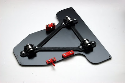
This is the new Y-carriage I built:
The carriage is made from 3mm composite sheet material, commonly known as DiBond. It's a plastic sandwich between two light sheets of aluminium. It's very strong and very light. I happened to find some in a black finish. This plate acts as both the mounting board for the bearings and the support board for the heated bed. This simplifies the construction and overall weight of the y-carriage. I used bearing mounts that have been joined by a simple triangle to position them (
http://www.thingiverse.com/thing:19771). There's a huge variety of y-carriage bearing holders on thingiverse, some have integrated belt clamps, some without. I just transferred my existing belt clamp and tensioner, and my opto-endstop flag.
The composite sheet material was marked out and cut with a jigsaw, using a fine toothed blade. All the holes were carefully marked and drilled. The three holes to support the heated bed were taped to take M3 bolts, to allow a Nophead style mounting and adjusting method which he talks about
here. I also adopted the insulation and cabling method he describes and utilises on his Mendel90 printer.
Wiring the heated bed:
The version MK2a (note the 'a') of the
PCB Heatedbed has larger soldering tabs as well as the middle hole. Given I wanted to position the middle hole over the single bearing it meant my ribbon cable needed to take a 90Deg turn to position the loop it in the direction of bed movement. The photo above also shows how I soldered on the ribbon cable and attached the thermistor. The exposed contacts were covered with some tape to prevent shorting on the foil insulation which will sit beneath.
I cut a piece of corrugated cardboard and glued on some kitched foil to make an insulator for under the heatedbed.
The foil faced cardboard sits between the carriage and the PCB heatedbed. To secure the ribbon cable I cut a piece pvc tube to protect the ribbon cable from the edges when I used a small buldog clip to clamp it in place. See photo below.
(note the adjustment screw above was not what I settled on.)
The adjustment screws were made up as follows. I took a long M3 spacer nut, thread-locked a headless screw into one end, and cut a screw to fit the other end. (I use a small disc in a Dremel to cut bolts/screws to length.)
I wanted 'soft' washers to pad the lock-screw. The corner of the PCB is quite delicate and I suspect easily broken. To make some PTFE washers, I pushed some PTFE tube through a hole in scrap piece of wood, and used a sharp chisel to cut as many washers as I needed.
Below is a photo of the adjuster screw/nut It works by loosening the top lock-screw, then turning the long nut to raise or lower the board, then tightening the lock-screw when done.
Here's the newly assembled y-carriage and PCB Heated bed. I cut a piece of picture frame glass to size for initial trials with PLA. I may have to get something better for ABS. There's a bit more work to do before I start into ABS. I want to build a hood and extractor next.
Conclusions:
The bed levelling process is so much easier with only three height adjusters. Start on the right, level front and back, then move to the left centre screw and adjust it until until the bed is levelled in a left/right direction. I level off the print-head tip, and perform the exercise with motors off moving x and y carriages by hand.
Raising the y-smooth rods to their top position only results is a small loss in z-height because the new layout has one less support plate. The original smaller board/plate that held the bearings is no longer required.
The use of
Triffid_hunter's bar clamps allowed the rods to sit on the threaded rod, giving a print bed that was almost level before any adjustment. The amount of final adjustment needed with this construction is extremely little.
The whole assembly is much lighter than my previous one. The loss of one board and the introduction of the composite sheet material has contributed to this. The net benefit of a lighter y-carriage assembly is greater print speeds with less strain on the motors or less risk of skipping due to inertia.
That's all for now. Thanks for viewing!
NumberSix


